Test equipment · Structural analysis
Test fixture crosshead
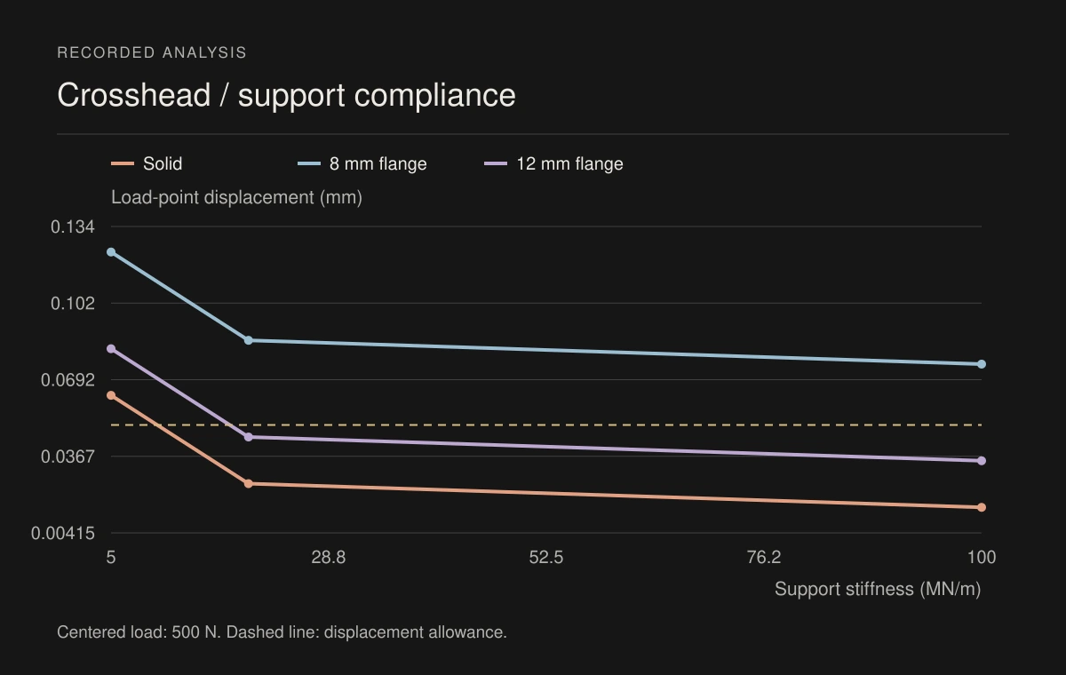
A comparison of three test-fixture crossheads under centered and offset loads. The analysis includes how much the supports contribute to measured movement.
Structural analysis with completed installation study
Implementation
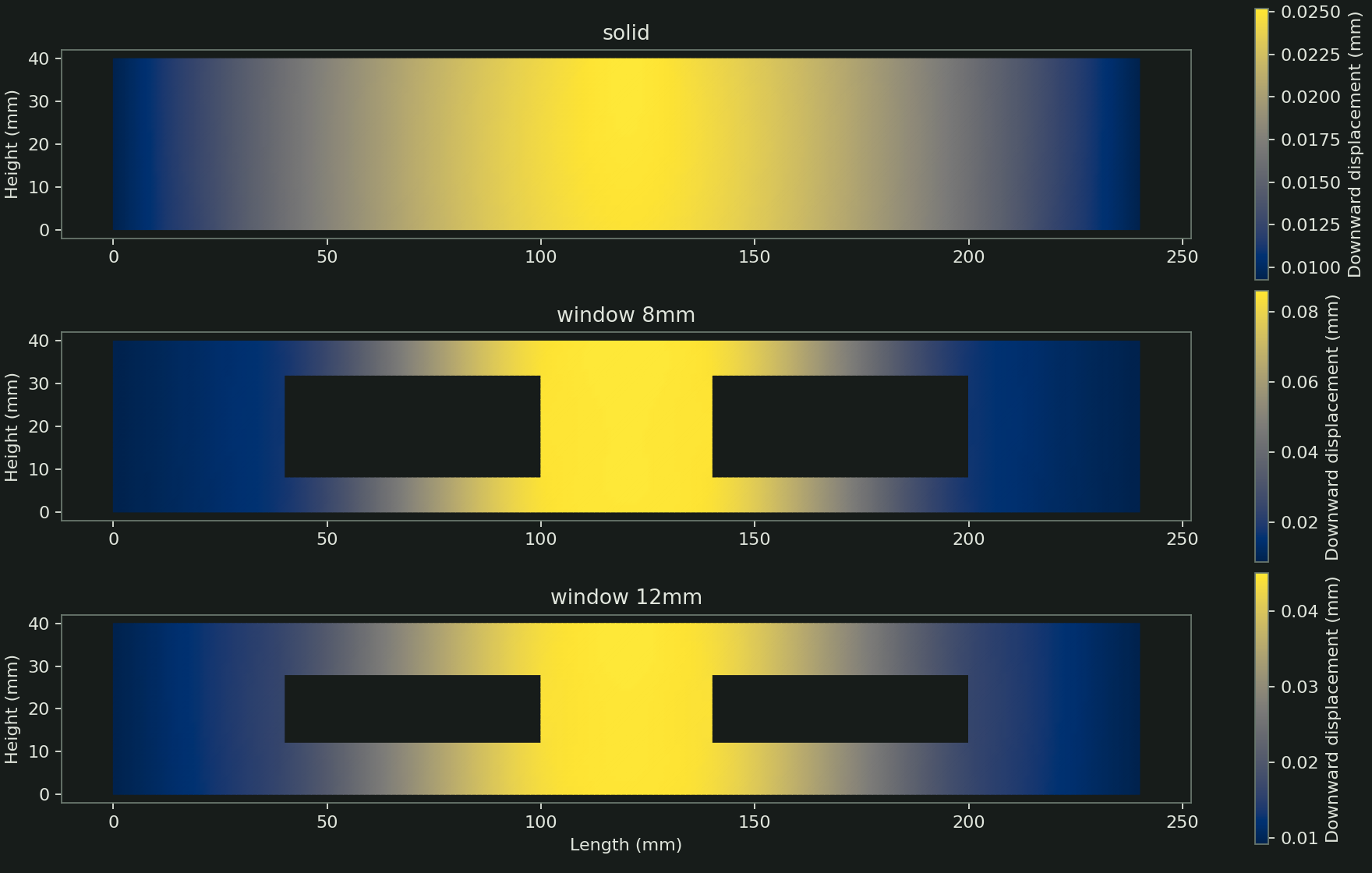
Quadratic triangular finite elements with distributed loads and spring supports.
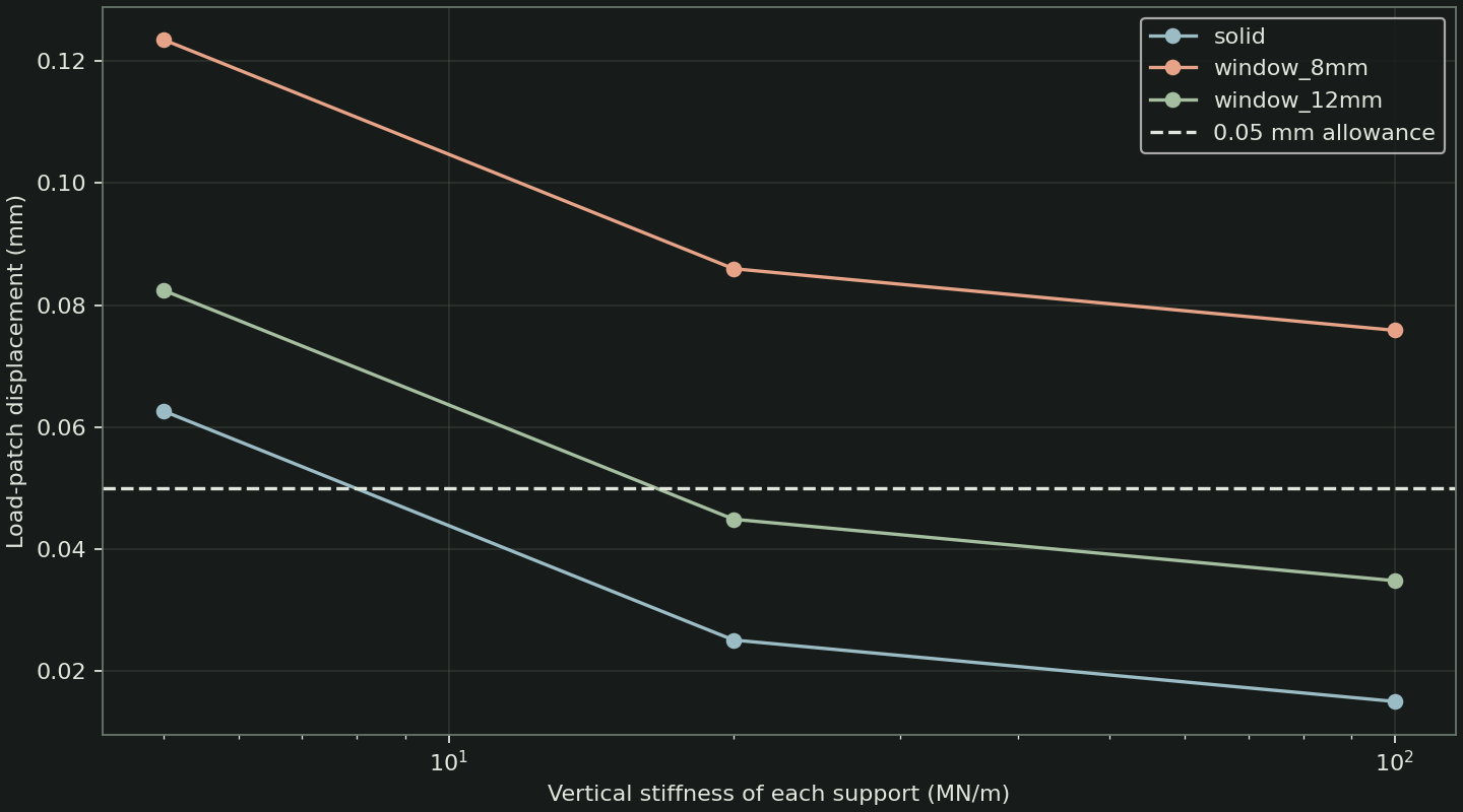
Centered and eccentric 500 N cases across three support stiffnesses.
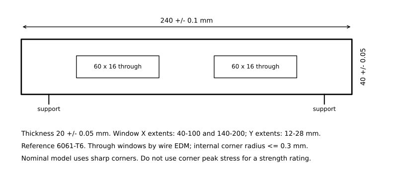
CAD exports and a dimensioned drawing for the selected windowed reference geometry.
Completed 20000 bounded input combinations, a calibrated compliance model, reduced-order out-of-plane torsion screening and 33 synthetic load-cycle readings.
The final installation envelope specifies 30 MN/m vertical and 500 N m/rad rotational stiffness per support; weak mounts and larger offsets remain rejected cases.
Inputs and assumptions
- 6061-type reference elastic properties: E 69 GPa, nu 0.33; constant 20 mm thickness.
- Declared support stiffnesses are sensitivity inputs, not measured hardware.
Results
Crosshead support stiffness
Compare the included analysis results.
| Load/support cases | 18 |
|---|---|
| Nominal selected displacement | 0.04488 mm |
| Mass reduction | 20.0 % |
| Weak-support target | Not met |
| Synthetic input combinations | 20000 |
| Selected vertical mount stiffness | 30 MN/m |
| Selected rotational mount stiffness | 500 N m/rad |
Report figures (2)
Verification
43 executed checks pass; regression tests and invalid-input checks are recorded separately. 11 commissioning acceptance checks and 7 additional regressions pass. The selected combined translational/torsional envelope stays below 0.05 mm including a 0.0001 mm response-fit allowance.
python run.py && python test_project.py && python complete_validation.py && python test_completion.pyAdditional scenarios
11 outcomes checked through synthetic/theoretical. The report lists the expected and observed outcomes for each check.
Read the validation report ↗Project files
The ZIP contains the source, inputs, results, and instructions. These files are also available individually.
- Finite element solversolver.py · 5 KB
- Geometry and load inputsinputs.json · 1 KB
- All load casesoutputs/load-cases.csv · 4 KB
- Mesh convergenceoutputs/mesh-convergence.csv · 2 KB
- Selected CAD modeloutputs/cad/window_12mm.step · 41 KB
- Dimensioned reference drawingoutputs/selected-drawing.svg · 44 KB
- Structural reportreport.html · 7 KB
- Accepted combined installation envelopecompletion/selected-operating-envelope.csv · 1 KB
- 20000 synthetic combinationscompletion/synthetic-envelope.csv · 2.1 MB
- Out-of-plane torque and mount sensitivitycompletion/out-of-plane-screen.csv · 1 KB
- Executed commissioning and fault studycompletion/report.html · 13 KB
- Completion acceptance matrix and source hashescompletion.json · 6 KB
- Reproduce the commissioning studycomplete_validation.py · 14 KB
- Declared commissioning inputscompletion-inputs.json · 1 KB
Archive checksum
SHA-256
bf5d4d482001f45c86c25c660acb05d41f5a486dad036de3b02ed140176ec55aOriginal project scope
Archived brief PDF ↗Run locally
Python 3.12 / scikit-fem 12.0.2 / SciPy 1.17.0 / NumPy 2.3.5 / CadQuery 2.7.0 / Matplotlib 3.10.8
Extract the ZIP and open a terminal in the test-fixture-crosshead folder. The README includes setup and usage details.
python -m pip install -r requirements.txt
python run.py
python test_project.py
python complete_validation.py
python test_completion.py
Limits
- Primary FEA is 2D plane stress with constant nominal 20 mm thickness. A separate reduced-order torsion screen evaluates through-thickness load offset; it does not resolve 3D joints or contact.
- The selected support stiffnesses are required model inputs, not measured hardware properties. The accepted envelope and rejected support cases are both documented.
- Ideal sharp-window corners are excluded from reported finite stress. Declared stress multipliers do not establish notch fatigue strength or a load rating.
- Synthetic input distributions and load-cell readings test analysis/data-reduction behavior. They are not manufacturing capability or physical FEA correlation.